基于矢量数据的拓展功能开发流程
通过拓展工具箱可以在项目中自定义开发基于点、线、面的矢量对象的处理工具,操作方式是首先导入矢量数据,在对象的右键菜单中激活拓展功能,找到对应的工具项进行操作。
面图层:VSpatialPolygonLayer
线图层:VSpatialPathLayer
点图层:VSpatialPointLayer
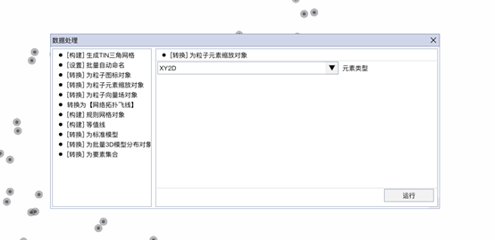
根据工具的复杂程度,UI上有所不同。一般分两种,通用和自定义。
通用型工具开发流程:
1.新建一个类继承自 mTooler
这种方式设计上比较方便灵活。
2.重写DrawInner,这里写入UI相关的代码。
1 | protected override void DrawInner() |
3.重写Process,完成点击[运行]按钮后执行的代码,这里传入的对象和this.fTarget是同一对象,使用中用哪个都行。如果有些工具不适合用运行的名称,可以在该类的构造函数中,指定按钮的名称。如
1 | this.mBntRunName = "数据处理"; |
1 | public override void Process(VSpatialPointLayer line) |
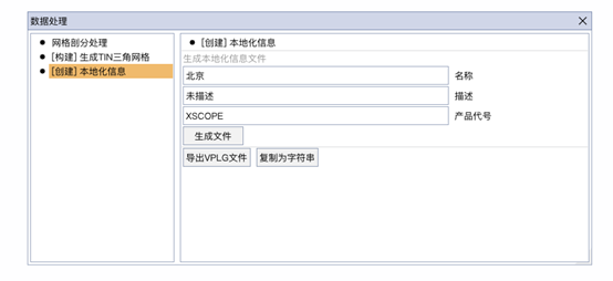
自定义工具开发流程:
最直观的理解是没有运行按钮,自定义UI,区别于通用型开发流程,无需理会Process,除非自己UI中执行了Process。UI在DrawContent中重写。
1 | public override void DrawContent() |
示例代码1:点图层转换为粒子元素对象
1 | public class tMultiPointWidgetToSprite : mTooler<VSpatialPointLayer> |
示例代码2:面数据转换为建筑数据
1 | public class tMultiPolygonToSectionModelSet : mTooler<VSpatialPolygonLayer> |
示例代码3:线图层转换为线集合对象
1 | public class tMultiLineToSingleLineGroup : mTooler<VSpatialPathLayer> |
示例代码4:面对象本地化信息输出
1 | public class tPolygonToLocationPatch : mTooler<IPolygonEditor> |